Master Slave Flip-Flop
We have used Feedback Inputs in JK flip flop. these feedback paths raised a new problem in the circuit, which is called race around condition. Race around condition in the JK flip is a major problem in which the outputs of flip flop are toggled continuously till the end of applied clock signal.
To avoid the problem of race around conditions in JK flip flop, we can use the Master-Slave Flip Flop.
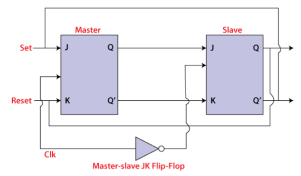
Master Slave Flip Flop is a combination of two JK flip flops which are connected in the cascaded manner as shown in figure below.
Block Diagram of Master Slave Flip Flop

In this combination of two JK flip flop, one acts as a master flip flop and the other acts as a slave flip flop. In this master-slave flip flop, the outputs of the master flip flop are connected to the inputs of the slave flip flop.
The outputs of the slave flip flop are fed back to the inputs of the master flip flop.
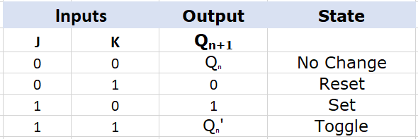
The following is the truth table of the master-slave JK flip flop

Working of Master Slave Flip Flop
- When the clock pulse goes to high, the slave flip flop becomes inactive and the inputs J and K can control the state of the system.
- When the clock pulse goes back to low, the information is transferred from master flip flop to the slave flip flop, and the final output of the system is obtained.
- Firstly the master flip flop is positive level triggered and the slave flip flop is negative level triggered, so the master responds before the slave.
- If J=0 and K=1, the high Q’ output of the master goes to the K input of the slave and the clock forces the slave to reset, thus the slave copies the master.
- If J=1 and K=0, the high Q output of the master goes to the J input of the slave and the Negative transition of the clock sets the slave, copying the master.
- If J=1 and K=1, it toggles on the positive transition of the clock and thus the slave toggles on the negative transition of the clock.
- If J=0 and K=0, the flip flop is disabled and Q remains unchanged.
Timing Diagram of a Master Flip Flop:

- When the clock pulse set to 1, the output of the master flip flop will be one until the clock input remains 0.
- When the clock pulse becomes high again, then the master’s output is 0, which will be set to 1 when the clock becomes one again.
- The master flip flop is operational when the clock pulse is 1. The slave’s output remains 0 until the clock is not set to 0 because the slave flip flop is not operational.
- The slave flip flop is operational when the clock pulse is 0. The output of the master remains one until the clock is not set to 0 again.
- Toggling occurs during the entire process because the output changes once in the cycle.


