J-K Flip Flop
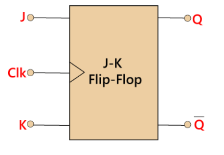
The JK flip flop is one of the most used flip flops in digital circuits. The JK flip flop is a universal flip flop having two inputs ‘J’ and ‘K’.
JK Flip flop is known as Jack Kilby flip-flop, it is versatile and can be used as a basic memory element.
JK flip flop has two modes of operation which are synchronous mode and asynchronous mode
In synchronous mode, the state will be changed with the clock(clk) signal, and in asynchronous mode, the change of state is independent from its clock signal
Block Diagram

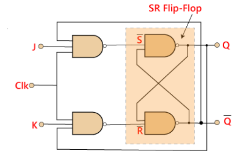
Circuit Diagram

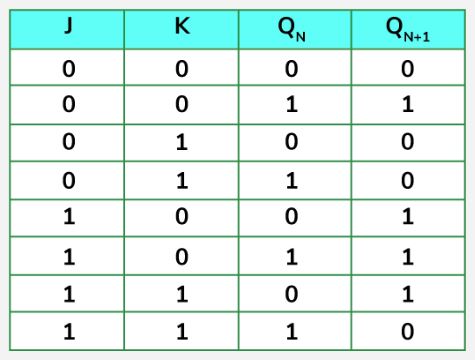
Truth Table

Then the JK flip-flop is basically an SR flip flop with feedback which enables only one of its two input terminals, either SET or RESET to be active
The JK flip flop is an improved clocked SR flip flop. But it still suffers from the “race” problem. This problem occurs when the state of the output Q is changed before the clock input’s timing pulse has time to go “Off”
Boolean Equation
Q̅n+1 = K̅Qn + JQ̅n
Applications of JK Flip Flop
- Counters
- Shift Registers
- Memory Units
- Frequency Division


